Why I Built My Own Wood Boiler Monitor
My brother Theo heats his place with an outdoor wood boiler in rural Alberta. It’s a Central Boiler E-Classic 2400, sitting on a concrete pad about 20 meters (60 feet) from the house. 1,287 liters (340 gallons) of water capacity, 76 kW (260,000 BTU/hr) max output. Two hydronic loops run from it - one to the house, one to the barn - each with its own circulator pump. The house has a natural gas furnace as backup, but it stays shut off when the boiler is running.
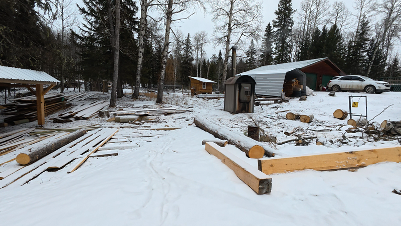 The E-Classic 2400 on its pad, about 20 meters (60 feet) from the house
The problem is simple: when the fire goes out overnight, you don’t find out right away. What happens is the furnace fan keeps blowing, trying to push heat that isn’t there anymore. You wake up at 3am because the air coming out of the vents is lukewarm and the fan hasn’t stopped running. Then you get dressed, walk out in the dark at way below -30C (-22F), and reload the firebox.
It’s not catastrophic - between the boiler, the pipes, and the heat exchangers, the system holds well over 1,287 liters of water at around 80C (176F). That’s a lot of thermal energy. Everything is at least somewhat insulated, and the house has natural gas backup if it gets really cold. But it’s the kind of thing where you’d rather get a notification on your phone than find out because you’re cold.
Theo asked if there was something that could just monitor the temperatures and alert when things drop. I said I’d build one.
Before the monitor
Theo tried pointing a WiFi camera at the boiler’s control panel to read the temperature display remotely. It sort of worked, but the image was hard to read, and it didn’t alert you when something was wrong. You still had to remember to check.
The property runs on Starlink - surprisingly fast and more stable than you’d expect, but power outages happen more often out there than in town. When the power goes, the internet goes with it. Any monitoring solution that depends on a server in the house or a cloud service is only as reliable as the weakest link in the chain - and there are a lot of links between a boiler in the yard and a phone on a nightstand.
So whatever I built needed to work on its own. Read sensors, decide when something is wrong, and send the alert directly - WiFi if it’s available, cellular if it’s not.
The build
I started about two months ago with a LILYGO T-SIM7080-S3 - an ESP32-S3 board with an onboard LTE modem for cellular fallback. A few DS18B20 temperature probes in stainless steel housings, and a CT clamp on each pump’s power line. The temperature probes tell you what the water is doing. The current clamps tell you whether the pumps are actually running. That was Theo’s ask - temperatures and alerts. The pump monitoring was my idea. Seemed like useful information to have.
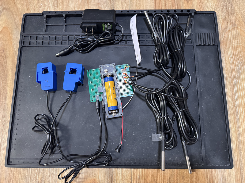 Work in progress - the LILYGO board, CT clamps, temperature probes, and wiring before assembly
The first version was bare minimum. Read sensors, publish to MQTT, send a Telegram message when the supply temperature drops below a threshold. It worked within a couple of evenings.
Then I kept going. Not because I had to - the basic version was already doing what Theo needed. But each thing I added made it more interesting:
- I wanted to change config without reflashing - JSON config on the filesystem
- I wanted to update firmware remotely - OTA updates over HTTPS
- I wanted flexible alert rules without recompiling - Lua scripting engine
- I wanted to see what’s happening live - web dashboard, MQTT for Home Assistant, shell over serial and MQTT
- I wanted it to work on different hardware - a module system where each board gets a different combination of sensors
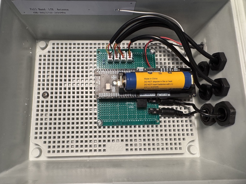 Work in progress - assembled in a waterproof project case, ready to mount
Two months in, it’s a real firmware platform. Not because I planned it that way - because each feature was fun to build and I could reuse it on the next board.
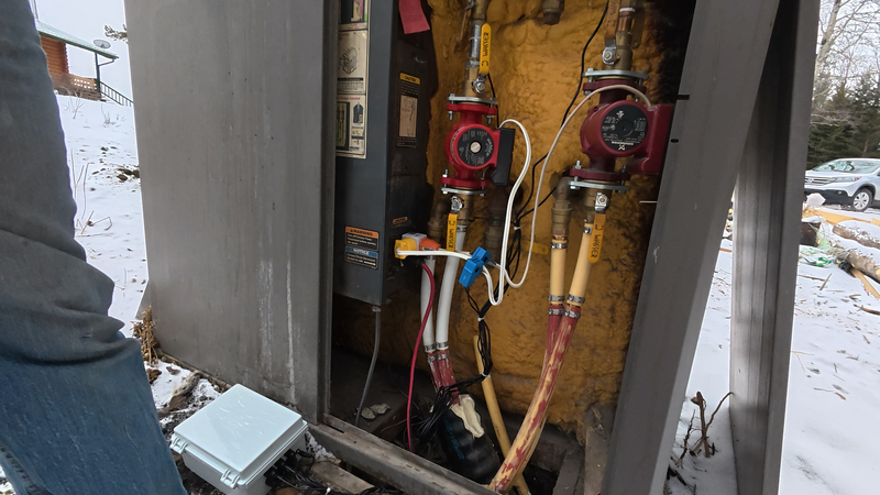 Work in progress - temperature probes and CT clamps installed on the supply and return lines
What I learned
WiFi reaches further than I expected. The boiler is in a sheet metal enclosure, which I assumed would kill the signal. The LILYGO board sits outside in a waterproof project case, and the WiFi signal is around -88 dBm - on paper that’s terrible. In practice, it holds. I added the cellular module expecting to need it for WiFi failures, but it mostly triggers during power outages and Starlink hiccups instead.
Cellular adds complexity. The IoT SIM costs about $15 a year for 1GB, more than enough for telemetry. But the SIM7080 modem and its AT command interface are finicky. Connection timing, registration delays, TLS handshake quirks. I’d say a disproportionate amount of firmware time went into making cellular reliable. Worth it for the fallback, but not free.
Power outages are the real failure mode. Not WiFi, not the boiler itself. When the power goes, everything goes - router, Starlink, the boiler’s own circulation pumps. The board has a small LiPo battery - enough to send a “power is out” alert and keep monitoring for a while until things come back or someone notices.
Heap management on embedded is its own discipline. The ESP32-S3 has about 512KB of working memory (RAM) for everything - your code, your variables, your network buffers, everything the program is actively doing. Once you add TLS encryption, MQTT messaging, OTA update buffers, a Lua scripting engine, a web dashboard, and a cellular modem driver, that memory gets fragmented. Think of it like a parking lot where cars keep arriving and leaving - eventually you have enough total space but not enough in one contiguous block for the next car. The S3 also has 8MB of slower PSRAM which helps offload some of the bigger allocations, but keeping things stable under sustained load is still a work in progress. It works, but I wouldn’t call it solved.
Is this a product?
No. It’s a hobby project that I built because I could and because my brother was happy to let me try.
I’d already been working with the ESP32 platform on other projects, so the tooling was familiar. Why not ESPHome or Tasmota? Both are great projects. But honestly, I did it because I could. I wanted to build something from scratch and this was a good excuse. Having full control over the networking stack - standalone alerting over cellular, custom OTA, direct Telegram integration - that’s a bonus. The real reason is that writing firmware is more fun than configuring someone else’s framework.
The firmware grew into something more general along the way - I adapted it to work with all the different boards I had laying around at home. A small touchscreen display on the desk, an Ethernet-connected sensor node, a bare dev board on the bench. Same firmware, different modules enabled per board.
There are commercial monitoring solutions out there - they work fine for most people. But none of them did exactly what we wanted: standalone operation without a cloud dependency, cellular fallback, flexible alerting, and the ability to add whatever sensor makes sense next. So I built it.
As it evolved, I moved the firmware from a private repository to a public one on GitHub. It’s not polished documentation-wise, but the code is there if anyone wants to look at it or build on it. More of the project may follow as things mature.
It’s a hobby. I build it in the evenings because I enjoy it.
What’s next
Right now the boiler monitor alerts every few days when nobody has loaded wood and the supply temperature starts dropping. It’s more of a reminder than an emergency - but that’s exactly what Theo wanted. It works, and it hasn’t missed one yet.
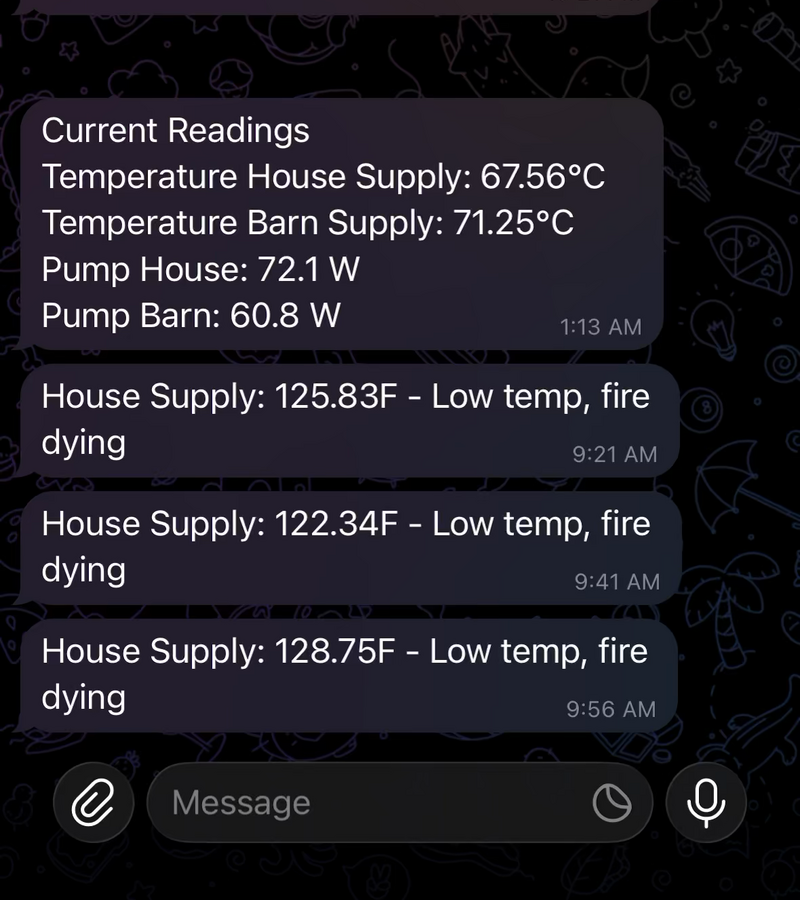
Work in progress - Telegram alerts showing temperature drops and pump power readings
The platform runs on a few different boards around the house for testing, but the boiler is the one that matters. There’s a custom PCB in the works to replace the dev board with something cleaner, and the firmware keeps getting new features when I find an evening to work on it.
Next up is a well pump monitor. Last year we discovered a leak in the water line from the deep well pump to the house - about 3 meters (10 feet) underground. It was a mess. A current clamp on the pump would have shown the duty cycle changing long before it became obvious. Same sensors, same firmware, different location.
If you’re interested in the project, the firmware is on GitHub. For technical details on the hardware and firmware, see the project documentation.